Support
Similar topics
- There are wrong limits in the test report for loop impedance and mains impedance measurements?
- Why does the fuse of the profi test sometimes drop when an RCD is tripped?
- Der RCD löst bei der Auslöseprüfung aus, aber es erscheint kein Messwert?
- Why does an error message appear when an RCD is tested with DC?
- Warum kommt eine Fehlermeldung, wenn ein RCD mit DC geprüft wird?
Can I measure the fault loop impedance across an RCD without tripping it?
(FAQ Nr. PG113)
31 March 2023 - 13:29
| PROFITEST MASTER, PROFITEST MF, PROFITEST PRIME | DC current, Loop impedance, RCD
First, the following information in advance: The measurement of the fault loop impedance ZL-PE and determination of the short-circuit current IK derived from it is carried out in order to check that the disconnection conditions for the miniature circuit-breaker are fulfilled in the event of a phase-to-earth fault. Before measuring the fault loop impedance, an electrical continuity test must be performed. According to DIN VDE 0100-600, no measurement of the loop impedance ZL-PE is required in circuits protected by RCDs, because in the event of a phase-to-earth short-circuit it is not the circuit breaker that trips, but the RCD, and the fault loop impedance is always considered to be fulfilled for its low tripping current. The correct function of the RCD and the mains impedance ZL-N must of course always be checked. If a residual current device (RCD) is used together for fault protection and additional protection, it is sufficient to consider the relevant requirements of DIN VDE 0100-410 for fault protection when testing the residual current device (RCD). Nevertheless, it is often desired to be able to measure the fault loop impedance in spite of the presence of the RCD, in order to provide indirect proof of the low-impedance connection of the PE conductor, since this is part of the loop. (Quality of the system) One wants to do without a separate (because of the additional cable to be laid to the PA somewhat more expensive) low impedance measurement RLO. There are now metrologically three possibilities: 1. measurement with low measuring current
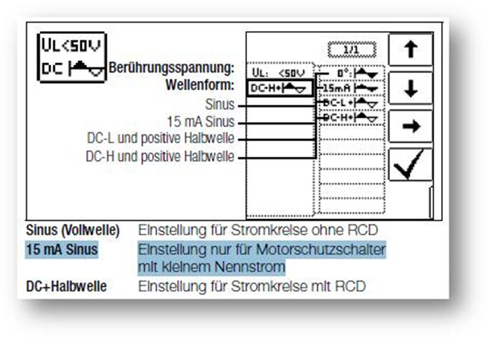
For the measurement of the loop impedance, the L-PE voltage is only loaded with a low AC current that is below the tripping threshold of the RCD - usually 15 mA. The resulting voltage drop △U and the △I = 15 mA are in turn used to calculate the loop impedance ZL-PE. However, with an impedance of e.g. 1 Ohm, the voltage reduction would amount to just 15 mV and since most test devices work in a measuring range of 600V here, it is clear that such small voltage changes cannot be measured accurately. Especially since the mains voltage can fluctuate even during the short measurement period of a few mains periods. Therefore, this measuring method only provides sufficiently accurate measured values at impedances >10 Ohm (see under Technical Data of the test instrument), corresponding to a short-circuit current IK of max. 23 A (@UN = 230V). This would still be sufficient for a miniature circuit breaker with characteristic B and a rated current of max. 4 A, i.e. practically only for overcurrent protection devices for individual loads such as motor circuit breakers.
 Although the test devices also display measured values for ZL-PE below 10 ohms and derived IK up to several hundred amperes with this measurement method, these are only informative. This can also be seen from the fact that repeated measurements on the same test object with low impedance provide strongly fluctuating measured values. Furthermore, the minimum measuring current of 200 mA required in the standard for low impedance measurements RLO would not be given.
2. Preventing RCD tripping by DC bias
 The ordinary RCD (type A or F) is first magnetically driven into saturation by a DC current, so that subsequently with the high measuring current (with half-waves of the same polarity) of several amperes, a sufficiently accurate measurement can be made even for low impedances, without the RCD tripping (although this cannot be guaranteed). This measurement also requires an N conductor connected to the test instrument. Of course, this trick does not work with all-current sensitive RCDs (type B and B+). 3. RLO measurement instead of loop impedance measurement
The DIN VDE 0100-600 standard allows a measurement of the protective conductor resistance (RLO) instead of the loop impedance for upstream RCDs.
© 2026 GMC Instruments. All rights reserved. | Imprint | Privacy Statement
This website is using cookies. More info.
That's Fine